Service Induced Failures
Fractures
Fractures in steels may propagate in one or more modes, dependent upon various factors which may include:
- Type of stress – tensile, shear, impact, cyclic, combination;
- Speed of loading – high speed, medium speed, slow speed, very slow speed;
- Temperature – high temperature, room temperature, low temperature;
- Environment – air, corrosive, protected, e.g. oil. The fracture mode itself may be either (a) ductile, (b) brittle; (c) fatigue; (d) combination.
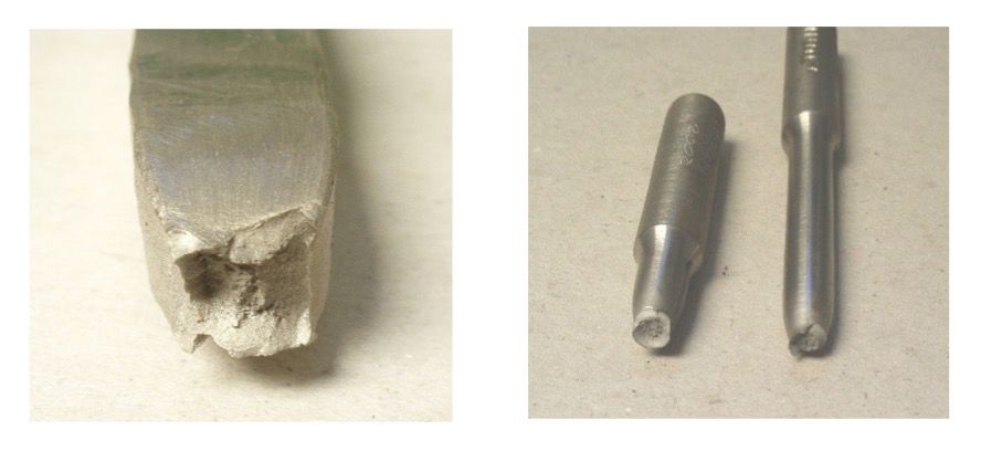
a. Ductile fractures
Ductile fractures always show plastic deformation usually at 45° angles to the load, the surface will exhibit a rough, fibrous appearance. In low carbon steels under test, e.g. tensile or bend, necking of the specimen will occur. Failure will usually be associated with the formation of shear lips.
• Brittle – The tendency of a material to fail suddenly by breaking without plastic deformation of the material before failure.
• Ductility – The ability of a material to be drawn into wire without fracture.
In tensile failures, the fracture surface may also show small dimples and peaks (cups and cones), these are caused by inclusions and voids.
A shear load would cause a fibrous fracture surface with well-defined shear lips:
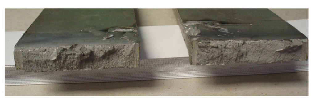
Compressive stress applied to a ductile steel will produce considerable metal spread and edge cracking:
Note: Ductile fractures which occur under dynamic loading (impact) have a dull grey appearance with extensive plastic deformation (shear lips) which would increase with the toughness of the material.
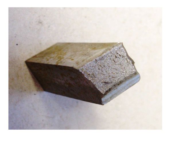
b. Brittle fractures
Brittle fractures occur with little or no plastic deformation. In general, high levels of stress and low temperature promote brittle fractures which may travel at very high speed at 90° to the load causing the formation of vees or chevrons which point backwards towards the point of initiation.
Brittle fractures which occur under dynamic loading, e.g. impact have a bright, shiny faceted or crystalline surface.
c. Fatigue cracking/fractures
Fatigue cracking is a service failure which occurs under cyclic stress conditions. It normally occurs at a change in section, e.g. groove, radius, step, weld toe etc., therefore design and workmanship are important to minimise failure by fatigue.
All materials are susceptible to fatigue failure. Since design and workmanship play a major part, ferrous based materials have an endurance limit applied to one grade of steel in a specific heat treated condition operating within specific parameters, below this limit fatigue is unlikely to occur. Other metals will all have the potential to fail by fatigue given the required conditions.
Fatigue failures start at a specific point and propagate with each stress cycle at a rate that depends on the applied stress. Fatigue failure is easily identified by beach markings on the fractured face. Final failure can be any other mode of fracture, e.g. brittle or ductile failure.
Thermal fatigue cracks may occur if the cyclic stresses are provided by frequent temperature changes producing fluctuating thermal stresses.
Corrosion fatigue failure results from a combination of cyclic stress and a corrosive environment at the fatigue site.
d. Combination modes
Fracture surfaces may exhibit one or more of the previously described modes of failure, e.g. fatigue, followed by either brittle or ductile failure. This is representative of a static (gradually) applied load as in a CTOD test or may show both ductile and brittle fracture modes as produced by dynamic (impact) loading as achieved for example in a charpy test.
Creep/creep failures
Deformation by creep is the slow plastic deformation of a metal, under a constant stress at any temperature. The plastic deformation is very small compared with normal tensile loading whilst the temperature range for creep in a given material is between 0.5 to 0.7 of its melting point expressed in Kelvin (K). Creep may lead to fracture.
The stages of creep are:
-
Primary creep
-
Secondary creep - steady state constant rate creep - the most important stage
-
Tertiary creep - the stage when the rate of extension accelerates and leads to failure.
Creep may occur in any situation where a steady state of stress exists, e.g. ranging from lead pipes at room temperature to steam and power generating plant at 450°C to 500°C.
Materials such as Cr-Mo-V have been developed for high temperature service which resist creep by blocking the plastic deformation slip systems.
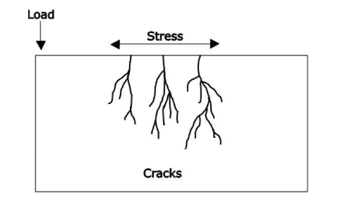
Stress corrosion cracking (Environmentally Assisted Cracking)
This type of cracking may occur in materials in a state of tensile stress and in contact with a corrosive medium. The level of stress which can cause the cracking may be well below the yield point of the material.
Stress corrosion cracks are surface breaking and are found at any sharp change in section, notch or crevice, especially in structures which have not been stress relieved. Both ferrous and non-ferrous materials are susceptible to stress corrosion cracking.